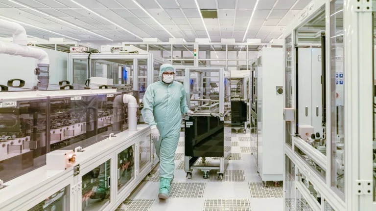
Designing modern pharmaceutical facilities, biotechnology pilot suites, and semiconductor cleanrooms requires strict environmental separation across controlled access boundaries. Among architectural contamination controls, deploying an automated cleanroom door interlock systems guide ensures that personnel and material transitions never compromise room cleanliness, room pressurization, or product integrity.
An electronic door interlock acts as the automated gatekeeper of an airlock. In high-containment laboratories and aseptic filling suites, manual operating discipline is insufficient to guarantee that two opposing doors never open at the same instant. By integrating electronic locking hardware, precision door position sensors, and programmed logical sequencing, an interlock system physically prevents cross-contamination, enforces air purge cycles, and maintains validated differential pressure cascades.
This technical engineering guide examines cleanroom door interlock architecture across operating principles, pneumatic cascade dynamics, regulatory mandates, control topologies, field wiring engineering, multi-door sequencing, life safety egress integration, and commissioning validation protocols.
The operator-facing view of that wiring is the sequence itself, mapped beat by beat in our guide to how a cleanroom airlock works.
The wiring is one layer; how that layer fails and gets overridden is walked through in our failsafe guide to cleanroom door safety systems.
How Door Interlocks Protect Cleanroom Environments
Differential pressure cascades represent the primary aerodynamic defense against airborne contamination in cleanroom manufacturing. Under international cleanroom standards, adjacent cleanliness grades must maintain static pressure differentials of 10 to 15 Pascals. This positive or negative pressure gradient guarantees that air leakage always flows in a controlled direction, protecting sensitive aseptic cores from less clean background environments.
When an airlock door opens, the static pressure barrier between rooms momentarily breaks down. Within 1.5 seconds of door unlatching, room pressure drops rapidly as air rushes through the open doorway. If operators open both airlock doors simultaneously, airflow vectors immediately equalize. This complete aerodynamic collapse permits ambient airborne dust, microbes, and aerosolized contaminants to enter the critical production zone.
An engineered cleanroom door interlock system enforces three critical environmental defenses:
- Preventing Aerodynamic Collapse: Guaranteeing that an airlock never becomes an open breach between differing cleanroom classifications.
- Enforcing HEPA Purge Intervals: Locking inner doors during a post-closure dwell time to allow HVAC air changes to flush newly introduced particulates.
- Stabilizing Facility Air Balancing: Preventing pressure oscillations that disrupt variable air volume (VAV) controllers across the wider cleanroom complex.
Pneumatic Cascade Integrity Principle
Simultaneous door opening drops airlock pressure to ambient within 1.2 seconds, inducing turbulence that takes up to 45 seconds to purge. Electronic interlock sequencing guarantees that airlocks never become an open aerodynamic conduit between differing cleanliness grades.
Basic Operating Principles of Cleanroom Interlocks
An architectural cleanroom door interlock operates on mutual exclusion logic. At its most fundamental level, the system monitors the mechanical position of two or more interconnected doors that form an airlock enclosure. When an operator pulls or releases Door A, the controller immediately detects the break in contact and commands the electromagnetic locks on Door B to remain energized. Access through Door B is strictly prevented until Door A returns to its fully closed, latched position.
Every industrial cleanroom interlock installation relies on three functional hardware layers:
- Position Sensing Devices: Magnetic reed switches or inductive proximity sensors embedded flush within frame reveals detect leaf contact without exposed physical levers.
- Electronic Locking Elements: Concealed electromagnetic shear locks or heavy-duty maglocks (300 kg to 600 kg holding force) providing positive physical holding power.
- Centralized Logic Controllers: Solid-state relay modules or programmable logic controllers (PLCs) executing interlocking state algorithms and timing routines.
Visual and acoustic status indicators provide critical feedback at each doorway entrance. Above or adjacent to each door frame, multi-color LED indicators display operational status. A steady green illumination informs operators that transit through the doorway is permitted. A steady red indicator signals that an opposing door stands open or that an active air purge cycle is in progress. Audible buzzers alert personnel if a door remains propped open beyond a pre-configured timeout threshold.
Modern electronic interlocks feature adjustable door-ajar timers to prevent intentional propping or prolonged transit delays. If an operator props a cleanroom door open with a wedge or transport cart for longer than 30 seconds, the local audio-visual buzzer escalates to a pulsating warning tone. Simultaneously, an alarm contact signals the facility monitoring network, prompting cleanroom supervisors to intervene before pressure cascading collapses.
Sensor engineering represents a decisive factor in preventing nuisance alarms. Conventional mechanical roller plunger switches accumulate dust and suffer from mechanical spring fatigue over time. Cleanroom doors utilize hermetically sealed magnetic reed switches or solid-state Hall-effect sensors embedded flush into the top frame reveal. The activating target magnet installs countersunk into the top edge of the door leaf. To accommodate slight door settling and HVAC pressure pulsations without triggering false open signals, the interlock controller firmware applies an electronic debounce filter of 50 to 100 milliseconds, verifying continuous contact before changing lock states.

Regulatory Compliance Under ISO and EU GMP
Pharmaceutical and biotechnology manufacturing facilities operate under stringent global regulatory oversight. Regulatory agencies recognize that physical airlock barriers represent critical contamination control points. Compliance inspectors scrutinize door interlocking design to ensure robust prevention of cross-contamination during personnel and material movement.
Cleanroom facility operators must comply with three primary international regulatory frameworks:
- EU GMP Annex 1 Section 4.10: Mandates that airlock doors must not be opened simultaneously and requires an electronic interlock system with visual and acoustic warning indicators for Grade A and B zones.
- FDA 21 CFR 211.42 cGMP Guidelines: Requires physical barriers and validated airflow separation to prevent contamination of sterile drug products during material and personnel transfer.
- ISO 14644-4 Annex A Standards: Specifies that airlock enclosures must incorporate interlocking mechanisms or operational procedures to isolate adjacent controlled environments during transit.
During regulatory audits, inspectors review IQ/OQ qualification documentation and alarm history logs. Facilities unable to furnish validated interlocking records or demonstrating frequent interlock bypass alarms face 483 inspection observations and potential batch discard liabilities.
| Regulatory Agency / Standard | Interlocking Requirement | Auditing Verification Method |
|---|---|---|
| EU GMP Annex 1 (2022 Revision) | Mandatory interlocking with optical/audio alarms | Simultaneous pull test & alarm verification |
| FDA 21 CFR Part 211.42 | Airflow separation and contamination prevention | Smoke visualization recovery decay curves |
| ISO 14644-4:2001 (Annex A) | Airlock isolation and sequence integrity | Commissioning functional qualification records |
| NFPA 101 Life Safety Code | Fail-safe egress release on fire alarm | Power cut simulation & fire relay drop test |
Hardwired Relay Systems vs PLC Controllers
When selecting control architecture, electrical engineers must choose between hardwired electromechanical relay logic boards and microprocessor-based Programmable Logic Controllers (PLCs). Both approaches offer distinct advantages depending on system size, facility complexity, and validation budgets.
Hardwired relay interlock boards utilize physical interposing relays, mechanical timers, and dedicated logic circuits to enforce mutual exclusion. Relay boards deliver unmatched reliability, immunity to software glitches, and straightforward troubleshooting for standard two-door or three-door airlocks. Because they contain no firmware or configurable software code, hardwired systems require minimal GAMP 5 software validation documentation, reducing initial engineering costs.
Programmable Logic Controllers (such as Siemens S7-1200 or Allen-Bradley Micro800 series) provide superior scalability for complex multi-room suites. PLCs execute sophisticated state machines capable of managing four or more doors, variable purge delay timing, priority dispatching, and bi-directional communications with building management systems via industrial Ethernet protocols.
Power supply sizing represents an essential calculation in control panel engineering. Each electromagnetic lock draws between 0.45 A and 0.65 A at 24V DC during continuous energized hold. For an airlock cluster supporting six interconnected doors, static current consumption reaches 3.9 Amperes, with transient inductive switching spikes drawing up to 8.0 Amperes. Engineers must specify industrial switch-mode power supplies (such as Mean Well DIN-rail units) with 150 percent headroom ratings, paired with uninterruptible power supply (UPS) battery backup modules capable of sustaining locking operations for at least 120 minutes during main facility brownouts.
| Technical Dimension | Hardwired Relay Boards | PLC Logic Controllers |
|---|---|---|
| System Scalability | Limited to 2–3 doors per module | Scalable to 16+ doors per controller |
| GAMP 5 Validation Burden | Category 1 / 2 (standard hardware) | Category 4 / 5 (configurable software) |
| Timing Flexibility | Potentiometer adjustments on board | Software parameters via HMI screen |
| BMS Network Integration | Dry contact relays only | Modbus TCP, BACnet, or OPC-UA |
| Mean Time Between Failures | High (millions of mechanical cycles) | Exceptional (solid-state electronics) |

Personnel and Material Airlock Sequencing Logic
Personnel Airlocks (PAL) and Material Airlocks (MAL) serve fundamentally different operational purposes and demand distinct interlocking sequences. Designing effective logic requires mapping exact movement protocols for staff gowning and pallet transfers.
Personnel gowning suites frequently utilize a three-stage progressive airlock: unclassified corridor, step-over bench changing zone, and classified manufacturing corridor. The interlocking controller must enforce unidirectional progression during shift start, preventing personnel from skipping gowning stages or moving backward across the step-over bench without redressing.
In a progressive three-door gowning airlock, the interlock state machine executes three sequenced transition rules:
- Rule 1 Primary Entry: Opening Door 1 (Corridor to Pre-Gowning) instantly locks Door 2 (Gowning to Sterile Corridor) and Door 3 (Emergency Exit), displaying steady red LED indicators on opposing leaves.
- Rule 2 Gowning Dwell Confirmation: Once Door 1 closes, the controller activates an internal timer (typically 45 to 60 seconds) ensuring the operator remains in the gowning zone long enough to don cleanroom garments properly before Door 2 permits touchless unlock.
- Rule 3 Egress Directional Reversal: During shift end, personnel moving in the exit direction trigger a reversed sequence, locking Door 1 until the operator crosses the step-over bench and de-gowns completely.
In biopharmaceutical facilities handling potent biological agents, airlocks often double as decontamination mist showers. When an operator steps inside the chamber and initiates the washdown cycle, the interlock locks both entry and exit doors for 90 to 120 seconds. Ceiling atomizing nozzles spray a fine aerosol of disinfectant mist followed by high-velocity dry air purging. Only after humidity sensors detect moisture clearance does the exit door release, guaranteeing complete bio-decontamination of operator suiting.
Material airlocks handling palletized components or equipment carts require automated sequencing coordinated with motorized clean room doors. A typical material transfer sequence follows four programmed steps:
- Stage 1 Outer Entry: The operator presents a credential, opening the outer sliding door; the inner cleanroom door locks immediately while amber status lights illuminate.
- Stage 2 Material Staging: The cart enters the airlock, and the outer door closes and latches, verified by concealed position sensors.
- Stage 3 HEPA Aeration Purge: High-velocity ceiling HEPA terminal diffusers initiate a 30-second particulate purge cycle while both doors remain locked.
- Stage 4 Clean Ingress: Once the purge cycle completes, the inner door unlocks automatically, displaying green indicators and permitting transit into the sterile production bay.
This automated handshake eliminates human error, guaranteeing that no material cart enters a sterile processing suite without completing its mandatory air wash cycle.
Field Wiring and Inductive Kickback Protection
Electrical installation errors represent the primary root cause of intermittent cleanroom interlock failures. Electromagnetic locks operate with large inductive coils. When power is removed to release a 600 kg holding force maglock, the collapsing magnetic field generates a back-EMF voltage spike exceeding several hundred volts.
If suppressing protection is absent, this inductive kickback arc damages relay contacts, induces electrical noise in adjacent sensor cables, and triggers spurious microprocessor resets. Installers must place flyback diodes (such as 1N4007) or metal oxide varistors (MOVs) directly across lock power terminals at the door frame, rather than inside the distant control cabinet.
Field wiring practices should adhere to three robust installation rules:
- Shielded Twisted-Pair Signal Routing: Run sensor input wiring in separate metal conduits isolated from 24V DC locking power lines to prevent capacitive noise coupling.
- Terminal Block Voltage Drop Calculations: Calculate conductor resistance to verify that maglocks receive at least 21.6V DC (within 10 percent of 24V nominal) under peak current loads.
- Flush Junction Box Sealing: House wiring splices in sealed back-boxes behind panel reveals, applying airtight silicone grommets to prevent air leakage through electrical conduits.
| Circuit Function | Conductor Specification | Maximum Cable Distance | Shielding & Noise Mitigation |
|---|---|---|---|
| Electromagnetic Lock Power (24V DC) | 2 x 1.5 mm² (16 AWG) stranded copper | 45 meters (<1.2V line drop) | Direct diode clamp at lock coil |
| Door Position Sensor (Reed Switch) | 2 x 0.5 mm² (20 AWG) twisted pair | 100 meters | Overall foil shield drained at panel |
| Touchless Wave Actuator / Sensor | 4 x 0.5 mm² (20 AWG) shielded | 60 meters | Isolated analog 24V supply circuit |
| LED Visual Indicator Pillar | 3 x 0.75 mm² (18 AWG) stranded | 80 meters | Common negative ground return |
| Emergency Break-Glass Circuit | 2 x 1.5 mm² (16 AWG) fire-rated | 50 meters | Hardwired series loop cutting coil power |
In addition, ground loops represent a common failure mode in modular sandwich panel facilities. Because anodized aluminum wall panels may not provide equipotential bonding, installers must tie the interlock control enclosure, power supply negative rail, and all cable shield drain wires to the main cleanroom technical ground bar at a single star-ground point. Floating shields or multi-point grounding creates circulating 50/60 Hz noise currents that trigger false door-ajar alarms during high-amperage autoclave and chiller startup cycles.
Inductive Kickback Warning
Never operate electromagnetic door locks without polarity-correct flyback diodes mounted directly at lock terminals. Voltage spikes from unsuppressed coils destroy control relays and trigger false emergency alarms.
Emergency Egress Protocols and Fail-Safe Wiring
While contamination control requires positive door interlocking, life safety regulations always take legal precedence over product cleanliness. Under NFPA 101 Life Safety Code and EN 13637 standards, building occupants must never be trapped inside an airlock during fire emergencies, seismic events, or toxic gas leaks.
Cleanroom interlock engineering must implement three redundant life safety mechanisms:
- Fire Alarm Interface (FAI Relay): A dedicated dry-contact relay from the building main fire alarm panel cuts 24V DC operating power to all maglocks simultaneously, immediately unlocking all doors.
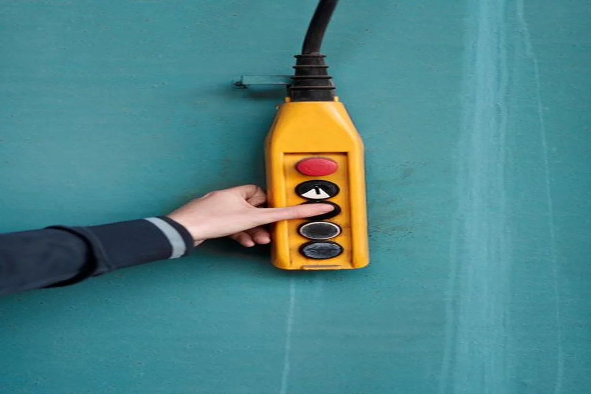
- Local Emergency Break-Glass Stations: Latching pneumatic or electrical push-to-exit buttons located on both sides of every door mechanically interrupt locking power independent of PLC logic.
- Fail-Safe Locking Hardware Architecture: All magnetic locks must be fail-safe (energized to lock), ensuring that complete power failure instantly drops holding force to zero.
Facility safety inspectors verify emergency egress compliance by performing live fire trip testing during annual cleanroom recertification audits. In addition to primary fire alarm relay drops, life safety codes require a physical mechanical override option on doors separating high-hazard chemical rooms. These mechanical push bars physically overcome magnetic holding resistance even if residual magnetism temporarily retains the armature plate. Interlock control panels must also incorporate a keyed master maintenance bypass switch, allowing engineering staff to de-energize all locks during major equipment move-in shutdowns without generating continuous nuisance alarms on the facility supervisory network.
Step-by-Step Commissioning and Validation Protocols
Cleanroom qualification mandates formal Installation Qualification (IQ) and Operational Qualification (OQ) protocols before an interlock system enters commercial manufacturing service:
- Perform Cold Mechanical and Wiring Inspection: Verify physical installation against schematic drawings, checking cable tagging, terminal torque, and flyback diode polarity.
- Execute Door Mutual Exclusion Functional Testing: Systematically open each door leaf and confirm that all opposing airlock doors enter locked states within 200 milliseconds.
- Verify Purge Dwell Timers and Door-Ajar Alarms: Measure post-closure purge delays using calibrated digital timers, and confirm that door-ajar buzzers trigger within plus or minus 1.0 second of configured limits.
- Conduct Smoke Pattern Visualization Testing: Generate visual non-toxic theatrical smoke along the closed door perimeter while HVAC operates at design velocities, verifying zero vortex entrainment across door seals.
- Conduct Live Emergency Egress Drop Tests: Trigger the main fire alarm relay and local break-glass stations under full door load, verifying instantaneous lock release across all leaves.
- Document As-Built Electrical and Functional Protocols: Archive test execution sheets, schematic diagrams, and PLC firmware checksums in the facility validation master file.
Frequently Asked Questions
What happens to cleanroom door interlocks during a power failure?
Cleanroom interlock systems utilize fail-safe electromagnetic locks that require continuous electrical power to stay locked. During a power failure, holding magnets de-energize instantly, allowing occupants to push doors open manually for unobstructed emergency egress under NFPA 101.
Can an interlock system handle three or more doors in a gowning suite?
Yes. Programmable Logic Controllers (PLCs) easily manage complex multi-door airlocks with 3 to 8 doors, enforcing directional sequencing, gowning protocol progression, and separate purge timing for personnel and material flows.
What is the standard purge delay time in cleanroom airlocks?
Purge delay times typically range from 15 to 45 seconds depending on airlock chamber volume, ceiling HEPA air change rates (often 40 to 60 air changes per hour), and cleanliness classification delta between adjacent rooms.
Are hardwired relay boards or PLC systems better for cleanroom interlocks?
Hardwired relay boards are ideal for simple 2-door airlocks due to lower capital cost and zero GAMP 5 software validation burden. PLCs are superior for complex multi-door suites requiring BMS network integration, adjustable timers, and data logging.
Why are flyback diodes essential on cleanroom electromagnetic door locks?
When an electromagnetic lock de-energizes, the collapsing magnetic field produces an inductive kickback spike of several hundred volts. Flyback diodes clamp this high-voltage transient, preventing damaged relay contacts and electronic noise in sensor circuits.