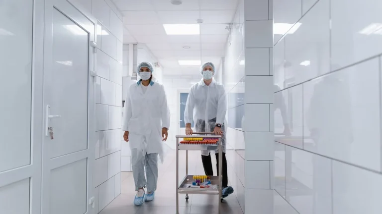
An uncoordinated airlock breach can compromise an entire sterile packaging campaign in less than three seconds. When two opposing containment doors unlatch simultaneously, pressure cascades collapse and airborne particulates bypass the protective air barrier. RAX Door Technology has engineered cleanroom closures since 1999 across our 11,000-square-meter facility. Operating under ISO 9001:2015 and CE EN 13241 standards, we formulate interlocking architectures that enforce rigid transit protocols without creating egress bottlenecks.
The operational premise of cleanroom double door interlock logic is straightforward yet unforgiving: under no standard condition may opposing airlock barriers open concurrently. Preventing simultaneous opening mitigates cross-contamination, preserves HVAC cascades, and stops airborne particulate ingress into sterile production suites. Dependable operation demands precision synchronization between microprocessor controllers, magnetic locks, optical door sensors, and emergency override loops.
Core Interlock Architecture in Controlled Environments
Modern cleanroom door interlocking architectures divide into two primary engineering methodologies: decentralized hardwired relay logic and centralized programmable logic controller (PLC) systems. Relay-based architectures utilize electromechanical or solid-state relays interconnected directly between door position switches and magnetic locks. When Door A unlatches, auxiliary contacts break the power circuit supplying the lock on Door B, establishing a hardware-level lockout. Evaluating these hardware topologies against ISO 14644-4 design parameters and HSE workplace health and safety risk assessment principles ensures continuous compliance across mission-critical facilities.
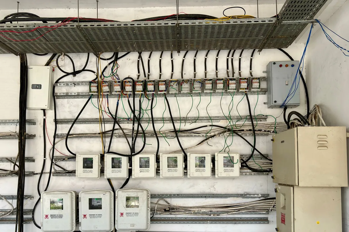
Centralized PLC architectures utilize digital input and output modules monitored by microprocessor logic. Digital sensors transmit door position, lock engagement status, and request-to-exit commands to the controller, which executes programmed sequencing routines. Specifying engineers compare key hardware parameters across control architectures to determine long-term operational viability.
Electrical safety and noise immunity are critical design considerations when routing multi-conductor control cables through cleanroom partition cavities. High-frequency electrical interference emitted by adjacent fan filter unit brushless motors can induce transient voltage spikes onto low-voltage sensor lines. To isolate microprocessors from field wiring noise, RAX Door interlock control panels incorporate optocoupled digital inputs providing 2,500 volts of galvanic isolation. In addition, regulated linear power supplies with overvoltage and reverse polarity protection prevent ground loops from destabilizing room pressure instrumentation.
| Engineering Parameter | Hardwired Relay Logic | Dedicated Microcontroller | Industrial PLC Architecture |
|---|---|---|---|
| System Response Latency | 15 to 30 milliseconds | 5 to 10 milliseconds | 1 to 5 milliseconds |
| Field Configuration Flexibility | Low (Physical Rewiring) | Moderate (DIP Switch Selection) | High (Software Modification) |
| BMS Network Telemetry | Dry Contact Signals Only | RS-485 / Modbus RTU | EtherNet/IP / BACnet IP |
| Mean Time Between Failures | 120,000 Operating Cycles | 250,000 Operating Cycles | 500,000+ Operating Cycles |
| Multi-Door Scalability | Limited (2 to 3 Doors) | Standard (Up to 8 Doors) | Extensive (16+ Complex Zones) |
PLC Ladder Logic and Boolean Interlock Matrix
Software and firmware logic in cleanroom interlocks govern user traffic, buffer purge timing, and alarm states. In standard personnel airlocks, basic Boolean logic enforces strict mutual exclusivity. In ladder logic programs, the control rungs evaluate door magnetic reed switches continuously to determine whether to energize holding coils.
The primary ladder logic equations follow two core conditional rungs:
- Rung 1 (Lock Control Door 1): [NOT Door_2_Open_Sensor] AND [System_Enabled] AND [Fire_Alarm_Healthy] = Output Lock_1_Energized
- Rung 2 (Lock Control Door 2): [NOT Door_1_Open_Sensor] AND [System_Enabled] AND [Fire_Alarm_Healthy] = Output Lock_2_Energized
In material transfer airlocks equipped with dynamic HEPA laminar purge or UV-C decontamination cycles, controllers incorporate programmable delay timers ranging from 15 to 180 seconds. Both doors remain locked until airborne particulate counts subside.
At RAX Door Technology, our 20-engineer technical team configures pre-wired interlock panels with dual independent watchdog microprocessors. This ensures that electrical faults or transient voltage spikes cannot cause simultaneous door release during live operations.
Custom Interlocked Cleanroom Airlock Engineering
RAX Door Technology designs and manufactures pre-wired interlock panels, electromagnetic shear locks, and failsafe cleanroom barrier systems tailored to your facility floorplans.
Consult an Interlock SpecialistCleanroom engineers should review our foundational analysis in the cleanroom pass box interlocked doors guide to understand how miniature transfer chambers apply identical electronic logic rules at smaller material transfer scales.
Terminal Block Wiring and 24VDC Power Distribution
Field hardware installation requires robust wiring practices to withstand EMI noise generated by cleanroom fan filter units and variable frequency drives. Electromagnetic shear locks and face-to-face holding magnets provide sanitary locking without mechanical strike cavities that harbor microbes. Magnetic locks rated between 300 kg and 600 kg holding force require continuous 12VDC or 24VDC filtered regulated power, drawing between 250 mA and 500 mA per unit.
High-integrity cleanroom installations utilize double-pole double-throw (DPDT) magnetic reed switches concealed within the door frame header. Conductor selection directly impacts signal integrity over long conduit runs across sprawling industrial facilities.
- Power Distribution Conductors
- Minimum 18 AWG twisted shielded pair wiring reduces voltage drop across runs exceeding 30 meters from the central 24VDC supply.
- Sensor Signal Cabling
- 22 AWG multi-conductor cable with overall foil shield prevents false open-circuit readings caused by adjacent motor interference.
- Transient Suppression Diodes
- Flyback diodes installed across DC magnetic lock coils clamp inductive voltage spikes during rapid de-energization cycles.
- Concealed Wire Transfer Hinges
- Armored continuous wire loops protect conductors passing from wall frames into specialized architectural cleanroom door systems.
Sensor reliability dictates overall interlock dependability. Single-point magnetic contact failures can falsely report a door as closed when it remains ajar, disabling interlock logic. High-containment suites mitigate this risk by deploying dual redundant sensing topologies. A concealed magnetic reed switch within the top header pairs with an auxiliary Hall-effect sensor in the latch pocket. The controller cross-references both inputs, and any discrepancy instantly locks opposing doors while sounding an alarm.
Airlock Differential Pressure Cascade Synchronization
Door interlock sequencing must closely correlate with building HVAC balancing strategies. When managing multi-stage cleanroom airlock pressure cascades, the sudden mechanical opening of a door releases a transient pulse of air into adjacent suites. Interlock controllers interface with building management systems to modulate supply air dampers during door openings, preventing differential pressure sensors from sounding false low-pressure alarms.

Integrating pressure threshold permissive switches ensures doors will not release if the differential pressure between chambers falls below 10 Pascals. For facilities requiring certified low perimeter air permeability under dynamic pressure swings, engineers should verify perimeter seals against EN 12207 airtightness classification standards.
To preserve cascade stability during rapid entry cycles, engineers configure the interlock controller to enforce four primary HVAC synchronization parameters:
- Purge Cycle Dwell Timing: Programmable delays of 15 to 45 seconds keep both doors locked following an entry cycle. This allows laminar airflow to scrub airborne particulates before the downstream barrier releases.
- Pre-Release Differential Verification: An analog input from room pressure transmitters confirms that cleanroom static pressure exceeds corridor pressure by at least 12.5 Pa before the door latch de-energizes.
- VAV Damper Feed-Forward Signaling: The controller transmits an advance dry contact pulse to the HVAC variable air volume controller 500 milliseconds before door unlatching, ramping up supply fan volume to offset opening envelope loss.
- Cascade Alarm Deadband Filtering: Integrating a 5-second transient filter into building management monitoring prevents brief door opening pressure fluctuations from triggering facility-wide deviation alarms.
Fail-Safe Fire Alarm Override and Emergency Breakout
Life safety requirements strictly supersede contamination control protocols. NFPA 101 Life Safety Code and local fire regulations mandate that all electromagnetic locks immediately release upon fire alarm activation, power disruption, or manual actuation of an emergency exit device. Power supplies driving interlock magnets must incorporate dry contact relay inputs tied directly to the central fire alarm control panel (FACP).
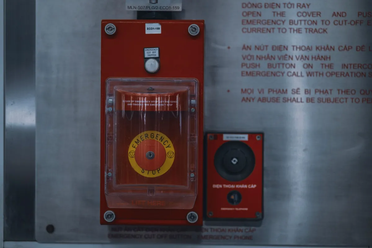
Emergency release circuits must utilize fail-safe normally closed (NC) wiring topologies. In the event of a severed conductor or system brownout, magnetic lock power disconnects instantly, granting unobstructed egress without human intervention. The 24VDC positive power supply rail routes directly through the FACP dry contact relay, ensuring hardware-level power cutoff.
| Operational Mode | Interlock Controller State | Magnetic Lock Power | Personnel Door Status |
|---|---|---|---|
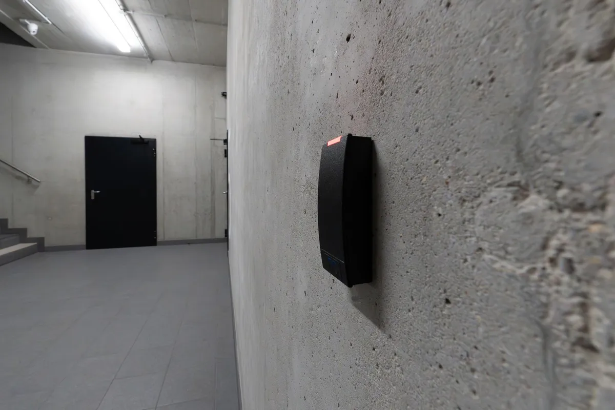
| Standard Quiescent Mode | Monitoring Both Doors Closed | Powered (Locks Armed) | Access via Card Reader / Wave Sensor |
| Active Transit Mode | Door A Open, Door B Locked | Door B Powered, Door A Released | One-way passage underway |
| Emergency Fire Alarm Trigger | FACP Relay Contact Open | Instant Power Cut to All Locks | Both Doors Free to Push Open |
| Localized Emergency Breakout | Manual Mushroom Button Depressed | Direct Hardware Cut to Local Door | Immediate manual breakout active |
Five-Step Commissioning and Validation SOP
Commissioning an interlocked door system requires methodical field verification before sterile manufacturing commences. Engineers must confirm that hardware alignments meet specified tolerances and that envelope leakage complies with rigorous engineering standards. Facilities follow a standardized five-step commissioning procedure during cleanroom qualification.
- Point-to-Point Conductor Verification: Measure continuity and ground isolation across all field terminations using a calibrated digital multimeter before energizing system power supplies.
- Lock Holding Force and Residual Magnetism Check: Verify minimum 300 kg pull resistance under rated voltage and test zero residual magnetic cling when power is removed.
- Interlock Logic State Confirmation: Attempt manual simultaneous opening of both doors to confirm mechanical lockout and illuminated LED status switching.
- Fire Alarm Loop Integration Test: Simulate a facility fire alarm contact trip and verify that all electromagnetic locks drop out within 200 milliseconds.
- BMS Differential Pressure Recovery Validation: Record room differential pressure decay and stabilization curves during repeated 30-cycle entry transit simulations.
Frequently Asked Questions
What is the difference between fail-safe and fail-secure cleanroom locks?
Fail-safe locks require continuous electrical power to remain locked; when power cuts, they automatically release to permit egress. Fail-secure locks remain locked during power loss. Cleanroom personnel airlocks universally mandate fail-safe magnetic locks for life safety.
Can a cleanroom interlock controller operate with three or four doors?
Yes. Centralized PLC or modular digital interlock controllers manage multi-door gowning rooms, three-way transfer airlocks, or complex cascade labyrinths. They program multi-zone interlocking matrices that lock multiple slave doors whenever one primary door opens.
How does an emergency breakout button override the interlock logic?
A cleanroom emergency breakout switch features hardwired normally closed contacts wired in series directly with the power supply line feeding the magnetic lock. Depressing the switch physically severs power locally, releasing the lock instantly without relying on software logic.
Why are electromagnetic shear locks preferred over mechanical strike locks?
Magnetic shear locks have no mechanical strike plates or internal springs that shed friction particles. Their smooth stainless steel housings integrate flush with door leaves, eliminating recessed microbial harbors.
How do interlock systems integrate with cleanroom differential pressure sensors?
Controllers accept dry contact inputs from pressure transmitters. If room differential pressure drops below design limits, the controller can inhibit door release or trigger an audible alarm until pressure cascades normalize.