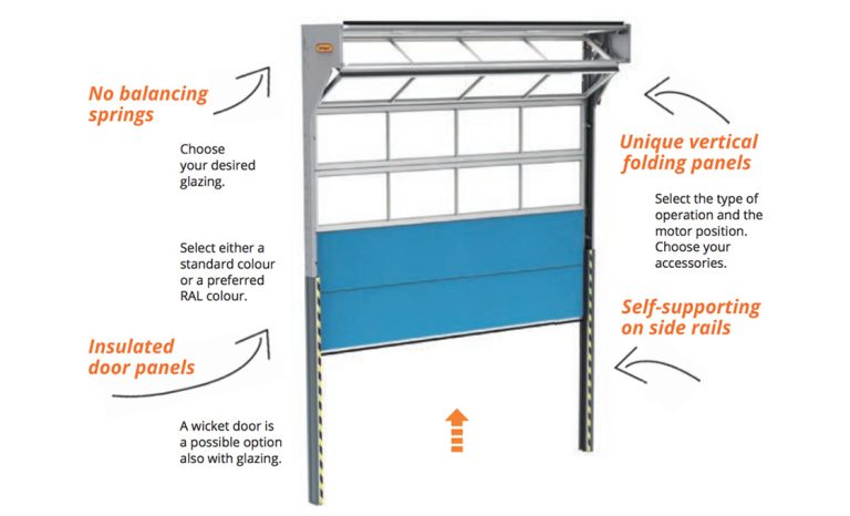
Automatic garage door openers are among the most convenient and frequently used electro-mechanical appliances in modern homes, operating between 1,500 and 2,500 times per year. With the simple press of a visor remote, a tap on a smartphone app, or a wall console button, an enormous 150 to 400-pound overhead sectional door glides open smoothly in less than 15 seconds.
Yet beneath that effortless motion lies a sophisticated combination of high-tension spring physics, radio frequency security, electric motor torque, reduction gearboxes, optical travel encoders, and multi-layered safety reversal circuits. Understanding how your garage door opener functions empowers you to perform routine maintenance, diagnose operational faults accurately, and ensure your system complies with mandatory safety standards.
Key Operating Principles at a Glance:
- Springs Do the Heavy Lifting: The counterbalance springs lift 90% to 95% of the door deadweight. The motor only supplies 10 to 20 lbs of directional guidance force.
- Encrypted RF Radio Signal: When you press the remote, a 315/390 MHz radio frequency transmitter sends an encrypted rolling security code to the logic board.
- Torque Multiplication: A high-speed electric motor spins a worm reduction gearbox to convert high RPMs into high pulling torque at a steady 7 to 9 inches per second.
- Active Dual Safety Reversal: Mandated by UL 325, the system continuously monitors infrared photo eye beams and motor electrical current to reverse immediately upon detecting obstructions.
The Counterbalance Secret: How Springs and Motors Work Together
The most common misconception regarding garage door openers is that the electric motor physically deadlifts the entire heavy weight of the door panels.
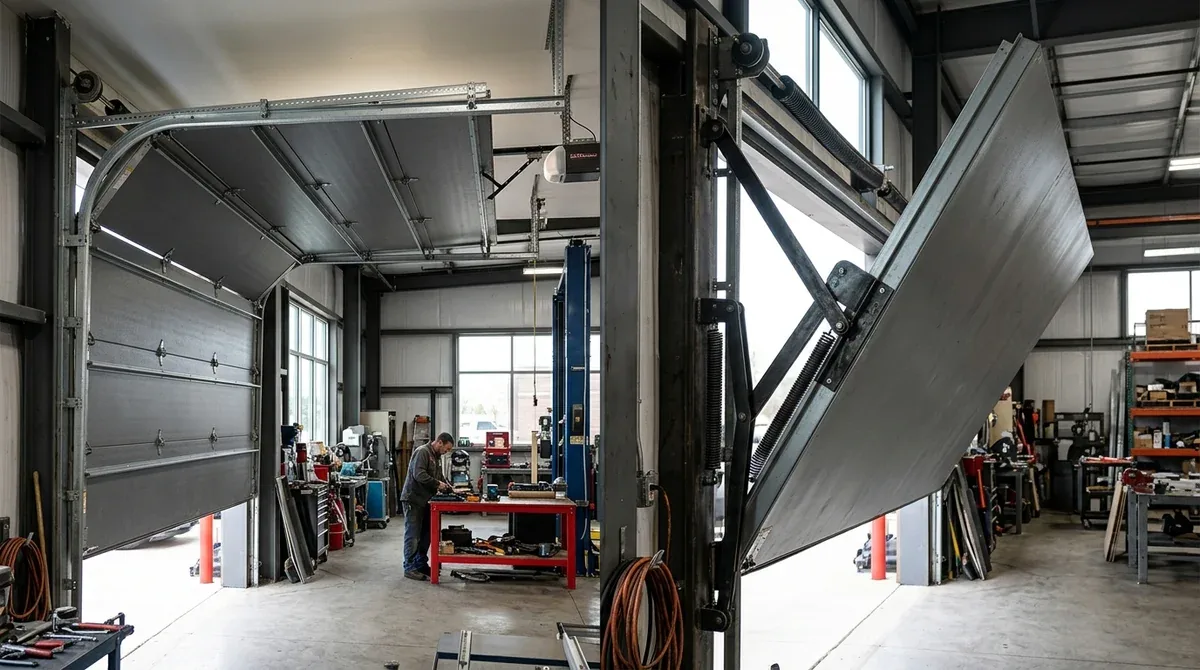
In reality, the heavy lifting is performed by counterbalance springs mounted above the door header (torsion springs) or along the ceiling tracks (extension springs). As the door closes, the descending weight winds the torsion springs, storing immense mechanical potential energy. When the door opens, the unwinding springs release that energy, neutralizing the panel weight so that a properly balanced 300-pound door feels like only 10 to 15 pounds to the operator.
The motorized powerhead acts as a precision governor. It initiates movement, regulates travel speed at 7 to 9 inches per second, stops the door at precise upper and lower limits, and locks the door securely against external forced entry when closed.
The 6-Step Operation Sequence: From Remote Click to Full Open
Every time you activate your garage door, the system executes a coordinated six-stage electro-mechanical sequence in fractions of a second.
- 1. RF Transmission & Security Handshake: The handheld remote or smartphone sends an encrypted rolling code over 315 MHz or 390 MHz radio frequency bands. The powerhead logic board decodes the transmission and validates the single-use cryptographic token.
- 2. Safety Circuit Health Check: Before energizing the drive motor, the microprocessor verifies that the infrared safety photo eye sensors are aligned and receiving an uninterrupted optical beam across the opening.
- 3. Motor Relay Activation & Soft-Start: The logic board energizes the motor circuit. On modern 24V DC openers, the controller applies pulse-width modulation (PWM) to ramp up motor speed smoothly over the first 12 inches of travel, eliminating track shudder.
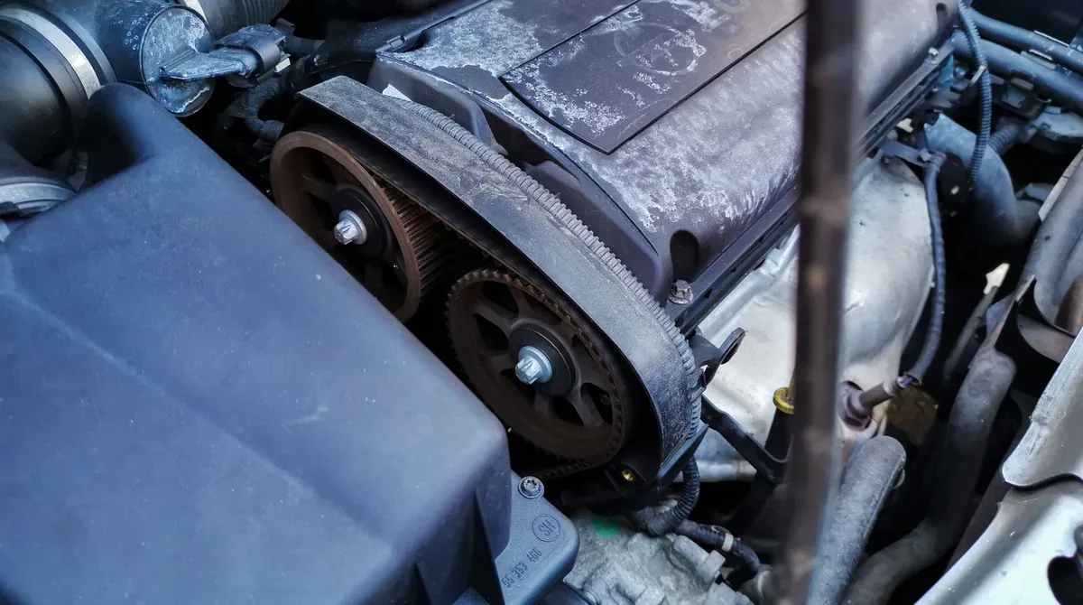
- 4. Torque Transfer & Trolley Travel: The spinning motor shaft drives the reduction gearbox, turning the drive sprocket. The belt or chain pulls the steel trolley carriage along the boom rail, lifting the door panels along the curved tracks.
- 5. Electronic Deceleration (Soft-Stop): As the door approaches the final 8 to 12 inches of travel, an optical rotary encoder detects the position and reduces motor voltage to softly cushion the final arrival.
- 6. Travel Limit Lock & Automatic Lighting: The motor shuts off, the worm gear locks the drive in place to prevent back-driving, and the integrated LED light remains illuminated for 4.5 minutes before turning off automatically.
How Different Drive Types Move the Door: Belt, Chain, Screw & Jackshaft
While all openers convert rotational motor torque into linear pulling motion, they utilize four distinct drive transmission mechanisms.

| Drive Transmission | Mechanical Linkage | Operating Sound Level | Key Engineering Advantage |
|---|---|---|---|
| Belt-Drive | Steel-reinforced polyurethane belt | Whisper-Quiet (<50 dBA) | Absorbs vibrations; zero lubrication required |
| Chain-Drive | ANSI #41 / #48 steel roller chain | Moderate (68 – 72 dBA) | Highest tensile strength; economical for detached shops |
| Screw-Drive | Direct threaded steel drive rod | Moderate (60 – 65 dBA) | Fewer moving parts; fast opening velocity |
| Wall-Mount Jackshaft | Direct torsion shaft coupling | Ultra-Quiet (<48 dBA) | Frees ceiling overhead space; ideal for high-lift tracks |
Inside the Powerhead: Electric Motors, Logic Boards & Gearboxes
The central ceiling powerhead houses the primary electro-mechanical intelligence and mechanical drive components.
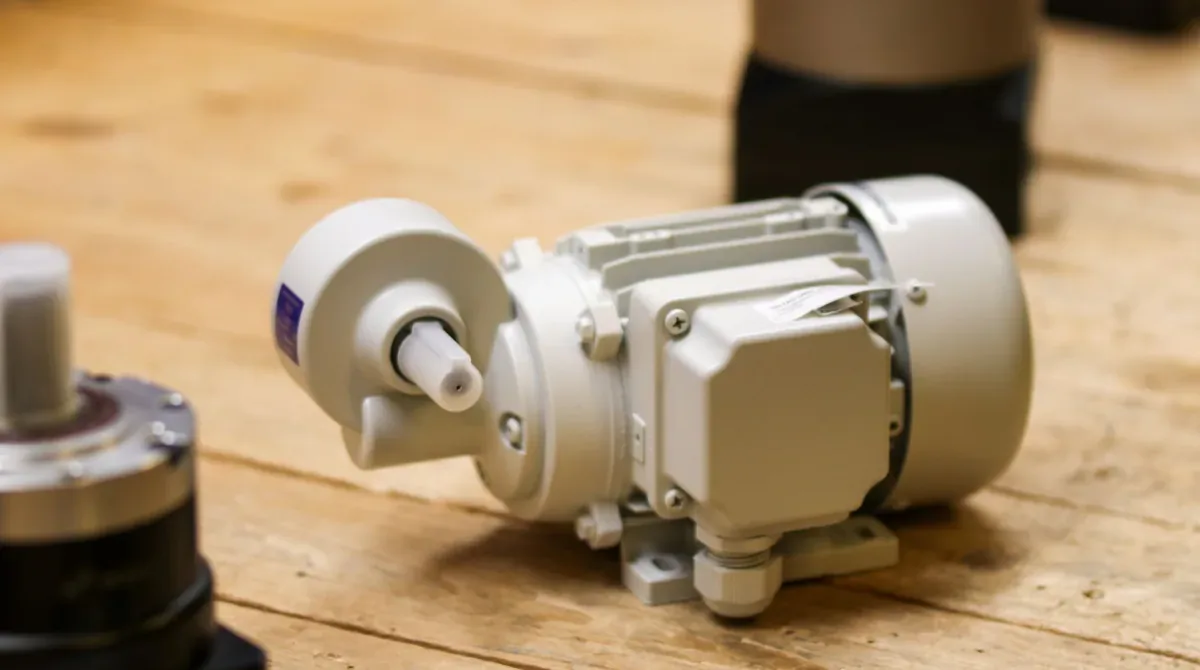
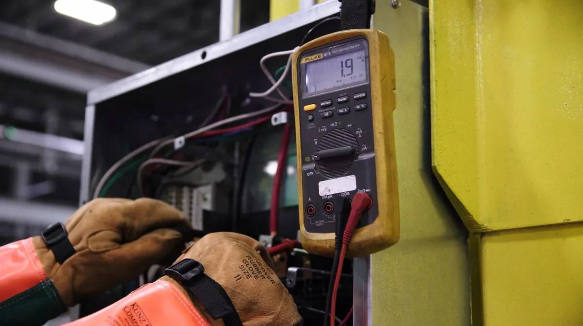
1. The Drive Motor (AC vs. 24V Brushless DC): Traditional openers use 120V AC induction motors that run at a single fixed speed. Modern premium openers utilize 24V Brushless DC (BLDC) motors that deliver higher starting torque, lower electrical energy consumption, and seamless battery backup integration.
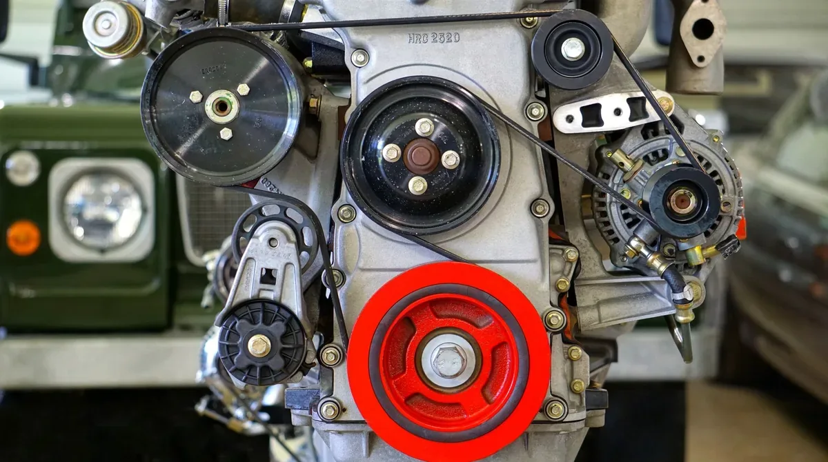
2. The Reduction Gearbox & Anti-Pry Lock: The electric motor spins at 1,500 to 2,000 RPM. A high-strength nylon helical reduction gear meshed with a hardened steel worm drive reduces this speed down to roughly 60 RPM while multiplying output torque by a factor of 30. Because a worm gearbox cannot be driven in reverse from the output shaft, it acts as an automatic mechanical deadbolt, preventing intruders from physically prying the door open from outside.
How Safety Auto-Reverse Systems Protect Your Family (UL 325)
Modern garage door openers are equipped with dual redundant safety auto-reverse systems mandated by federal safety standard UL 325.
- 1. Non-Contact Infrared Safety Sensors (Photo Eyes): Mounted 4 to 6 inches above the garage floor on both sides of the door tracks, an infrared sending eye projects a continuous invisible beam to a receiving eye. If a child, pet, or vehicle interrupts the beam while the door is closing, the logic board immediately stops travel and commands the motor to reverse to the fully open position.
- 2. Contact Mechanical Auto-Reversal: If the safety sensors fail or an object is struck above the sensor beam (such as the roof of a car), the logic board monitors the rotational resistance of the motor. When current draw spikes by more than 15 pounds of resistance, the microprocessor halts the door within 1.5 seconds and reverses travel.
How Travel Limits and Electronic Force Calibration Work
To seal tightly against the floor without crushing the weatherstripping, the opener must know exactly where the door is positioned at all times.
Mechanical Limit Screws vs. Digital Optical Encoders:
- Mechanical Limit Switches (Older Openers): Physical plastic contact sliders ride along a threaded steel screw shaft inside the chassis. Adjusting the limit requires turning slotted plastic screws with a flathead screwdriver.
- Digital Rotary Optical Encoders (Modern Openers): A slotted encoder wheel spins on the motor armature, monitored by an optical photodiode. The logic board counts individual shaft rotations with millimeter precision. Limits are set electronically using push buttons on the powerhead.
The Red Emergency Release Cord: How It Works & When to Use It
Every overhead garage door opener is equipped with a red emergency release handle hanging from the trolley carriage.

How to Operate the Emergency Disconnect:
- Disengaging for Manual Mode: When electrical power fails and your unit lacks a battery backup, pull the red cord straight down and back toward the motor. This retracts a spring-loaded metal pin from the drive trolley, allowing you to lift and lower the door manually.
- Re-Engaging the Automatic Opener: Push the red lever upward toward the door. When you next activate the motor or manually lift the door, the trolley will click and lock automatically back into the drive carriage.
Master Component Breakdown & Troubleshooting Guide
Use this quick diagnostic reference table to identify common symptoms and their mechanical root causes.
| Observed Symptom | Probable Root Cause | Recommended Corrective Action |
|---|---|---|
| Motor hums for 3 seconds, but chain/belt does not move | Stripped nylon helical gear or blown AC start capacitor | Replace internal drive gear kit or swap 50-70µF motor capacitor. |
| Door reverses immediately upon touching the floor | Down-travel limit set too far down; hitting floor too hard | Back off down-limit adjustment so bottom rubber seal compresses 1/2 inch. |
| Door won’t close; opener lights flash 10 times | Infrared photo eye misaligned, obstructed, or wire broken | Align sensor brackets until green/amber indicator LEDs glow solid. |
| Remote only works from 2 feet away | Weak remote battery or LED bulb radio frequency interference (RFI) | Replace CR2032 battery; install shielded garage door rated LED bulbs. |
| Motor runs, belt/chain moves, but door stays shut | Trolley carriage disconnected from emergency release lever | Flip emergency release arm upward and manually lift door until trolley snaps in. |
| Wall console push-button rapidly blinks green/yellow | Vacation lock switch on wall panel is engaged | Press and hold lock button for 3 seconds to re-enable remote radio reception. |
Frequently Asked Questions About How Garage Openers Work
Does a garage door opener lift the entire weight of the door?
No. The high-tension counterbalance springs (torsion or extension) lift 90% to 95% of the door deadweight. The electric opener motor only supplies 10 to 20 pounds of force to initiate movement, regulate travel speed, and control stopping limits.
How does a garage door opener reverse when an object is in the way?
Openers utilize two independent safety systems: non-contact infrared photo eye sensors near the floor that detect beam interruptions, and contact force-sensing circuits that detect increased motor electrical resistance if the door strikes an obstruction, immediately commanding the motor to reverse.
Why do garage door opener lights flash when the door refuses to close?
Flashing powerhead lights (typically 10 flashes) are a standardized diagnostic error code indicating that the infrared safety sensors are misaligned, obstructed, dirty, or experiencing a disconnected low-voltage wire.
How does the emergency release cord work during a power outage?
Pulling the red emergency cord disengages the spring-loaded lock pin inside the trolley carriage, freeing the garage door from the motorized chain or belt so you can manually lift and close the door by hand.
How do rolling codes protect my garage door opener from hacking?
Rolling-code radio technology generates a brand new, encrypted security code from billions of combinations every time you press your remote. Once a code is used to open the door, it becomes permanently invalid, preventing code grabbers from recording and replaying your remote transmission.