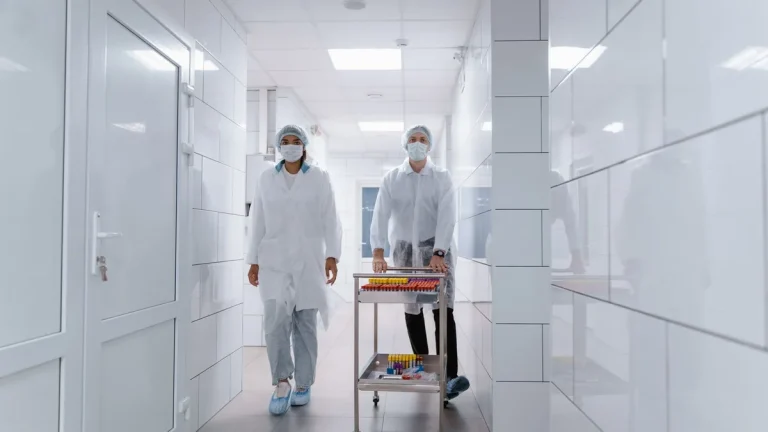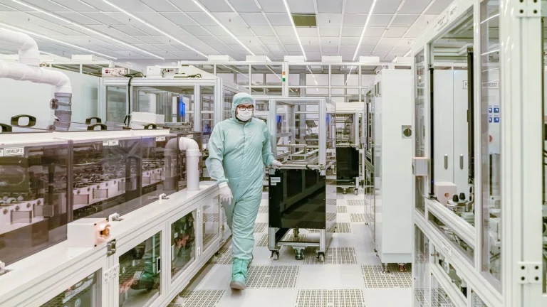
In high-grade pharmaceutical manufacturing, biotechnology pilot plants, semiconductor fabrication bays, and medical device packaging suites, airlocks serve as the critical physical and aerodynamic buffer between different environmental classifications. The engineered door assemblies installed on these high-traffic airlock chambers represent the single most critical, active mechanical barrier in the entire facility envelope.
Table of Contents
- Airlock Flow Regimes: Cascade, Bubble, and Sink Physics
- Automated 24V Interlocking and Purge Delay Dwell Logic
- EN 12426 Class 4 Airtight Sealing and Drop Gaskets
- Personnel Gowning vs Material Transfer Airlock Chambers
- Integrated HEPA Air Showers and Pass-Through Hatches
- Commissioning and Pressure Cascade Validation Protocols
- Cleanroom Airlock Doors Engineering Specification Matrix
- Request Engineering Consultation for Cleanroom Airlock Projects
Based on our engineering team’s extensive field experience designing, manufacturing, and commissioning ISO 14644 and cGMP Annex 1-compliant cleanroom hardware, improper airlock door specification or faulty interlocking logic causes immediate pressure cascade collapse, cross-contamination between adjacent zones, and severe regulatory audit non-conformities. This comprehensive technical guide analyzes the aerodynamic design, automated interlocking, perimeter sealing, and commissioning protocols for cleanroom airlock doors.
Seeing those doors as a moving sequence rather than static hardware is the focus of our guide on how does a cleanroom airlock work, one entry cycle at a time.

Airlock Flow Regimes: Cascade, Bubble, and Sink Physics
Controlled cleanroom airlocks utilize precisely calibrated and actively balanced differential air pressure regimes to prevent airborne micro-particulates and biological aerosols from migrating across classification boundaries.
“Under ISO 14644-4 and ISPE Baseline guidelines, cleanroom airlocks must maintain certified pressure differentials between 10 Pa and 15 Pa per classification step, utilizing specialized cascade, bubble, or sink aerodynamic regimes to protect critical processing zones while eliminating cross-contamination.”
Cascade Airlock Pressure Regimes for Progressive Cleanliness
Cascade airlocks represent the most common and standard engineering configuration for positive-pressure pharmaceutical cleanrooms and advanced biotechnology facilities where cleanrooms operate at higher pressure than external corridors:
- Progressive Pressure Drops (+45 Pa / +30 Pa / +15 Pa): Pressure decreases systematically from the inner Grade B core (+45 Pa), through the gowning airlock (+30 Pa), to the external corridor (+15 Pa).
- Outward Airflow Velocity Vector: Whenever an airlock door opens briefly, clean filtered air sweeps outward toward the dirtier zone, physically blocking airborne particle ingress.
- Airtight Door Compression: Outer and inner doors require EN 12426 Class 4 perimeter sealing to prevent uncontrolled air bleed from draining HVAC static pressure.
Bubble and Sink Airlocks for Hazardous Containment Isolation
When manufacturing potent compounds or containing hazardous biological agents (BSL-3/BSL-4), specialized pressure envelopes are mandatory:
Bubble vs Sink Aerodynamic Rules: A Bubble Airlock maintains higher pressure inside the chamber than both adjoining rooms (+30 Pa airlock vs +15 Pa rooms) to create a protective air barrier. A Sink Airlock maintains lower pressure inside the chamber (-15 Pa airlock vs 0 Pa rooms), pulling air inward from both sides to contain hazardous toxic aerosols.
Automated 24V Interlocking and Purge Delay Dwell Logic
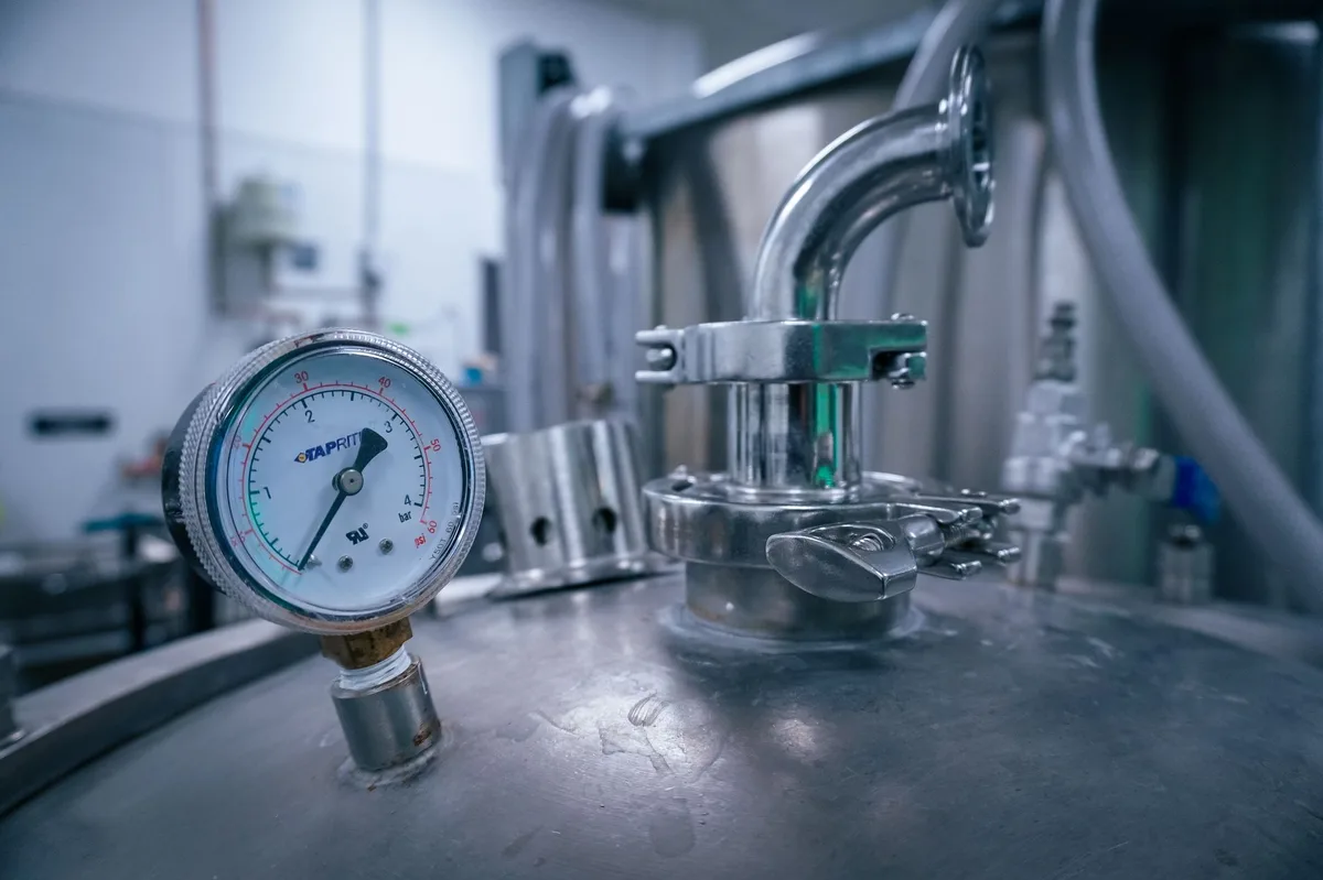
The primary operational and engineering failure mode in non-automated manual airlocks is simultaneous door opening by facility personnel, which instantly collapses calibrated room differential pressure cascades and allows turbulent airborne cross-contamination.
24V DC PLC Sequential Door Cycling Architecture
Cleanroom airlock doors incorporate electronic microprocessor interlocks to guarantee physical separation between cleanroom zones:
- Touchless Sensor Proximity Trigger: An operator triggers a narrow-beam optical wave switch within 50mm to 300mm proximity range.
- Opposing Door Electromagnetic Lockout: The central 24V DC PLC instantly energizes 600 lbs electromagnetic locks on opposing doors within 50 milliseconds.
- Door Leaf Release and Transit: The requested door unlatches, displaying a green illuminated LED ring indicator to permit personnel entry.
- Airlock Door Closure and Magnetic Verification: Heavy-duty overhead concealed closers return the door leaf to the frame, engaging magnetic reed status sensors.
HEPA Air Exchange Dwell Timing (30 to 60 Seconds)
Simply closing the entry door does not immediately restore certified cleanroom baseline cleanliness; human operators continuously shed millions of microscopic skin scales, particulate debris, and clothing fibers during gowning and transit:
- Programmable Purge Timer: The central PLC enforces a mandatory 30 to 60-second dwell time before unlocking the internal cleanroom door.
- High Volumetric Air Exchange: Dedicated ceiling HEPA fan filter units exchange 20 to 30 air volumes per minute, sweeping airborne particulates into low-level return air grilles.
- Visual Traffic Light Indication: High-visibility red/green LED status panels on both door leaves display real-time purge countdown status to operators.
EN 12426 Class 4 Airtight Sealing and Drop Gaskets
Without certified airtight perimeter seals, airlocks suffer continuous air leakage that disrupts facility balance.
Continuous Extruded Platinum-Cured Silicone Perimeter Gaskets
To eliminate continuous conditioned air bypass, cleanroom airlock doors utilize high-performance, precision-engineered multi-lip elastomeric silicone perimeter gaskets:
- Precision Dovetail Retention: Continuous silicone profiles press-fit directly into CNC-machined frame channels without organic adhesives that off-gas VOCs.
- Multi-Chamber Compression Profile: Dual hollow chambers compress smoothly under closing forces, restricting air leakage to under 0.5 m³/h per m² at 50 Pa static pressure.
- Biocide Chemical Resistance: Endures repeated exposure to 1,500 ppm vaporized hydrogen peroxide (VHP), sodium hypochlorite, and isopropyl alcohol under ASTM D543.
Concealed Bottom Scissor Drop Seals for Zero Friction Drag
To seal the bottom floor clearance gap without wearing rubber against resin flooring:
Drop Seal Kinematics: An internal mechanical scissor linkage drives a dual-fin silicone gasket straight downward 10mm only as the door leaf fully latches, compressing tightly against the epoxy floor with zero scraping drag during swing travel.

Airflow Recovery Kinetics and Cleanliness Decay Prevention
Opening an airlock door causes localized turbulent air exchange between rooms. Facility engineers must calculate airflow recovery times under ISO 14644-3:
- 100:1 Particle Decay Recovery Time: High-efficiency ceiling HEPA supply registers must restore baseline ISO Class 5 cleanliness within less than 15 minutes of door closure.
- High-Velocity Doorway Air Curtains: Optional non-turbulent downward laminar air curtains above door headers establish a continuous dynamic velocity barrier (0.45 m/s) whenever the door leaf opens.
- Low-Level Return Grille Geometry: Exhaust return air grilles positioned at finished floor level capture settling human skin scales and gowning lint before they reach breathing zones.
Personnel Gowning vs Material Transfer Airlock Chambers
Cleanroom architectural standards require separate airlock pathways for personnel movement and material equipment transfer.
Multi-Stage Personnel Gowning Airlocks (CNC -> Gowning -> Sterile)
Personnel gowning airlocks follow a strict multi-room unidirectional layout under cGMP Annex 1:
- Pre-Gowning CNC Zone: Personnel enter through interlocked doors to remove outdoor apparel and don primary hairnets and shoe covers.
- Gowning Transition Chamber: Features integrated stainless steel cross-over step benches dividing the pre-gowning and sterile zones.
- Sterile Core Entry Airlock: Operators complete sterile glove sanitization before interlocked cleanroom doors permit access into Grade A/B filling suites.
Automated Material Transfer Airlocks and Dynamic Pass Boxes
Material airlocks (MAL) accommodate palletized raw materials, cleanroom transfer carts, and sterile single-use processing equipment:
- Wide Clear Openings (Up to 2400mm): Double-swing or bi-parting automated sliding doors accommodate automated guided vehicles (AGV) and pallet jacks.
- Stainless Floor Strike Plates: Recessed 316L stainless steel floor plates protect epoxy resin floor joints from heavy cart wheel wear.
- Automated Rapid Roll Integration: High-traffic material airlocks utilize high-speed fabric roll-up doors operating at 2.0 m/s to minimize air exchange time.
Integrated HEPA Air Showers and Pass-Through Hatches
Dynamic air showers and pass-through boxes provide mechanical de-dusting before materials or personnel enter critical clean zones.
High-Velocity Nozzle De-Dusting (25 m/s Air Velocity)
Integrated dynamic cleanroom air shower chambers and de-dusting tunnels incorporate high-velocity HEPA-filtered clean air nozzles:
- Adjustable 316L Stainless Nozzles: High-pressure centrifugal blowers deliver HEPA-filtered air at 20 m/s to 25 m/s across operator garments.
- Mechanical Scrubbing Effect: High kinetic energy airflow dislodges surface-bound particulates, directing them into floor-level pre-filters.
- Interlock Cycle Enforcement: Both entrance and exit doors remain electromagnetically locked during the 15 to 30-second air shower cycle.
Interlocked Pass-Through Chambers with UV-C Germicidal Lamps
Small tools, samples, and sterile packaging enter cleanrooms through wall-mounted pass-through boxes:
UV-C Safety Interlock: Pass-through chambers equipped with 254nm UV-C germicidal disinfection lamps must feature safety cutoff micro-switches that instantly extinguish UV lamps if either chamber door is opened, protecting personnel from optical radiation.
Commissioning and Pressure Cascade Validation Protocols
Before cleanroom airlocks receive validation sign-off under ISO 14644-3, technicians execute rigorous commissioning procedures:
- Smoke Pencil Streamline Visualization: Generate theatrical smoke around door frames during opening and closing cycles to verify smooth laminar airflow without turbulent back-drafts.
- Pressure Cascade Decay Measurement: Open the outer airlock door and record room differential pressure recovery time, verifying recovery within 15 seconds.
- Interlock Override and Life Safety Verification: Simulate building fire alarm activation to confirm all 24V electromagnetic holding locks drop power within 50 milliseconds under NFPA 101.
- Optical Particle Counter Verification: Measure airborne particulate concentrations inside the airlock chamber following a 45-second HEPA purge cycle to confirm ISO Class 5 cleanliness baselines.
Pass-Through Box Mechanical Interlock Cam Mechanics
For small sample transfers where electrical wiring is impractical, cleanroom pass-through chambers utilize heavy-duty mechanical interlocking mechanisms:
- Internal Stainless Linkage Rods: Dual mechanical rocker arms link opposing stainless steel door handles through internal frame cavities.
- Rotational Cam Lockout: Rotating the handle on Door A drives an internal cam detent that physically blocks the latch mechanism of Door B from turning.
- 100% Fail-Safe Mechanical Separation: Requires zero electrical power, providing continuous interlock security even during total facility electrical outages.
- Magnetic Latch Tension Adjustment: Adjustable neodymium magnetic catches ensure continuous perimeter silicone gasket compression across both doors.
Acoustic Dampening and High-Frequency Noise Isolation (Rw 36 dB)
Continuous air showers and high-capacity HEPA fan filter units generate significant acoustic noise within confined airlock chambers:
- Acoustic Laboratory Rating (ISO 10140): 50mm composite aluminum honeycomb cores with high-density acoustic damping layers achieve certified Rw 34 dB to Rw 38 dB noise reduction.
- Acoustic Perimeter Sealing: Four-sided compression silicone gasketing and bottom drop seals prevent blower motor hum transmission into quiet analytical testing suites.
- Operator Ergonomics: Lowers interior ambient noise during air shower cycles, enhancing technician comfort during mandatory gowning procedures.
Routine Airlock Preventative Maintenance Schedules
To ensure uninterrupted interlock operation and prevent pressure cascade alarms, facility teams perform structured quarterly maintenance:
- Silicone Gasket Wear and Elasticity Inspection: Check continuous perimeter seals for chemical hardening, cracking, or particulate adhesion.
- Drop-Seal Compression Adjustment: Calibrate the bottom drop actuator plunger to ensure 3mm to 4mm uniform compression against the floor resin.
- PLC Interlock Cycle and Timer Diagnostic: Test and log sequential door interlock relays, optical wave sensors, and emergency fire power-cut circuits.
- Magnetic Holding Force Verification: Measure 24V electromagnetic lock pull-strength using a digital dynamometer to confirm >600 lbs holding force.
Cleanroom Airlock Doors Engineering Specification Matrix
The following engineering matrix compares technical specifications, airtightness ratings, and interlocking hardware across different cleanroom airlock door assemblies.
| Engineering Parameter | Personnel Gowning Airlock Door | Material Transfer Airlock Door | BSL-3/4 Biocontainment Airlock | Cleanroom Pass-Through Box |
|---|---|---|---|---|
| Target Cleanroom Classification | ISO Class 4 – ISO Class 7 | ISO Class 5 – ISO Class 8 | ISO Class 3 – ISO Class 5 | ISO Class 4 – ISO Class 7 |
| Airtightness (EN 12426) | Class 4 (<0.5 m³/h·m²) | Class 4 (<0.5 m³/h·m²) | Class 4+ (Gastight Seal) | Class 4 (<0.5 m³/h·m²) |
| Door Configuration | Single Swing Coplanar | Double Swing / Rapid Roll | Hermetic Sliding / Swing | Dual Interlocked Flaps |
| Face Panel Material | Solid HPL / 304 Stainless | Grade 304 / 316L Stainless | Grade 316L Stainless Steel | Grade 304 / 316L Stainless |
| Interlocking Control Logic | 24V PLC Microprocessor | 24V PLC Microprocessor | Redundant Safety PLC | Mechanical / Electronic |
| HEPA Purge Cycle Integration | 30 – 60s Dwell Timer | 45 – 90s Dwell Timer | Continuous Dynamic Purge | Optional UV-C / HEPA Purge |
| Emergency Egress Override | NFPA 101 Fail-Safe (<50ms) | NFPA 101 Fail-Safe (<50ms) | Keyed Manual Mechanical Egress | None (Pass Box Only) |
| Mechanical Durability Rating | >1,000,000 Cycles | >1,000,000 Cycles | >500,000 Cycles | >250,000 Cycles |
Frequently Asked Questions About Cleanroom Airlock Doors
What is the primary purpose of cleanroom airlock doors?
Cleanroom airlock doors maintain pressure differentials, prevent simultaneous door openings between clean and dirty zones, allow HEPA air showers to purge contaminants, and provide an airtight physical barrier under ISO 14644-4.
What is the difference between cascade, bubble, and sink airlocks?
Cascade airlocks feature higher pressure in the cleanroom flowing outward, bubble airlocks maintain highest pressure inside the airlock to create an air barrier, and sink airlocks maintain lowest pressure inside the airlock to trap hazardous bio-aerosols.
How do cleanroom airlock interlocking systems work?
Electronic 24V DC PLCs monitor magnetic door status sensors; when one door opens, the system energizes electromagnetic locks on opposing doors, preventing both doors from opening simultaneously until a purge cycle completes.
What is the typical HEPA purge delay time inside an airlock?
Under cGMP Annex 1 guidelines, airlock interlocks enforce a 30 to 60-second HEPA purge delay after door closure, allowing the ventilation system to exchange 20 to 30 room air volumes before unlocking the cleanroom entrance.
How do airlock doors comply with fire and life safety egress codes?
All 24V electromagnetic locks feature fail-safe power-cut relays compliant with NFPA 101, which drop holding power instantly upon fire alarm activation or local emergency break-glass actuation to allow free escape.
Request Engineering Consultation for Cleanroom Airlock Projects
Specifying high-performance cleanroom airlock doors engineered with certified EN 12426 Class 4 airtightness, automated 24V DC microprocessor interlocks, coplanar flush subframes, and dynamic HEPA purge controls guarantees sterile boundary integrity and complete cGMP Annex 1 compliance.
Our engineering division designs and manufactures custom modular cleanroom doors, automated airlock interlocking control panels, dynamic air shower enclosures, and stainless pass-through chambers tailored to ISO 14644 standards. Explore our complete clean room door product line or contact our cleanroom engineering specialists today to receive custom airlock PLC wiring schematics, BIM CAD models, and competitive project estimates.